In the following article we will introduce you to the free Kohler Power Solution Center software. If you are an electrical contractor, you will be able to have all the tools at hand to design a power generator tailored to the needs of your customer and then process the purchase of your generator at Brags & Hayes Generator. Send us your project documentation to info@bnhgenerators.com.
The software also has additional complementary tools that will allow you to approach your project in an integrated way. See the details below.
It is a software that allows the electrical engineer to calculate in a granular way the load for an application where a power generating source is required. Additionally, once the project load has been defined in detail, it allows you to select which generator has the appropriate characteristics for the project and also allows you to calculate the sound level of the ideal generator for your project — as well as the exhaust system piping, the pipe sizing for gas systems, genset and room size.
How can I get the Kohler Power Solution Center?
To download the software, click the button below:
Minimum system requirements: Windows 7 OS / 1024 x 768 screen resolution.
What can I do with the Kohler Power Solution Center?
The Kohler Power Solution Center handles the concept of projects. After your project settings have been set (default or new), and your projects have been saved, you will be directed to the Projects page upon start up. From the Projects page, below, you can navigate to or from an existing project as well as save or send a project. The Projects page can be accessed at any time, you may do so by clicking the Projects tab at the left of the program screen, as shown below. After your user profile is created, you can create, update, manage and delete as many projects as you need.
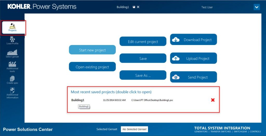
The Kohler Power Solution Center allows you to create a custom power system that will meet your facility’s needs.
The Load Profile tab is a drag-and-drop type of interface, starting with a default generator in place. Starting with a 3-Phase generator (or a 1-Phase generator selected in profile defaults), you can add electrical elements to your system by selecting the element from the Component Tool Bar. To add loads you can drag-and-drop the element type on top of the pre-positioned generator element (See figure below).
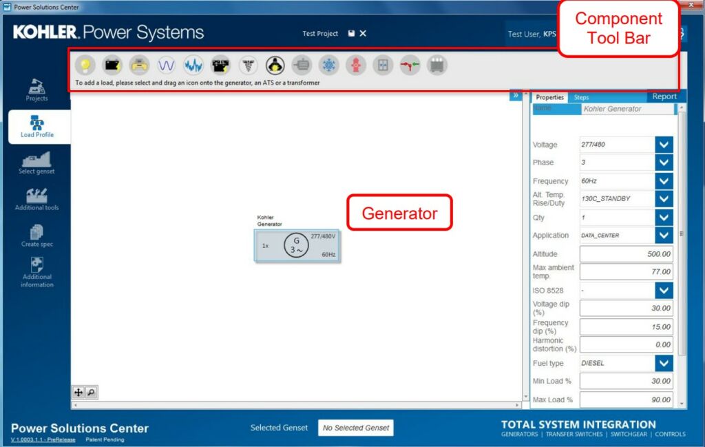
In order to start customizing your power system, you will need to add the different components that will be found in your facility and/or will be dependent upon your new generator. To customize your power system simply click, drag-n-drop (with your cursor) your desired component(s) from the Component Tool Bar, on top of the generator.
You can add the following loads with a simple drag and drop in order to calculate the total load that the generator of your project will require:
- Lighting Loads: Incandescent, Florescent, HID (high-intensity discharge), or LED. In addition to lamp wattages, ballast types, and starting and running power factors should be considered.
- Battery Charger Loads: A non-linear load requiring an oversized alternator based on the number of rectifiers. Typically found in telecommunications systems.
- Office Equipment: Computer(s), Printer(s)/Copier(s), Fax Machine(s), Paper Shredder(s), Telephone(s), etc.
- Misc. Linear Load.
- Misc. Non-Linear Load: Loads that change often resulting in spikes on the AC power. You may want to oversize the generator if these loads are expected.
- UPS (Uninterruptable Power Supply): A battery charger to maintain power in a bank of batteries, in the event of a power outage.
- Medical Equipment: These include CAT scan, MRI, and X-ray equipment. The generator set should be sized to limit voltage dip to 10% percent, or less, when operating with other loads running.
- Welder (Welding Equipment): Station(s), Welding Machine(s), Power Supplies, Jig(s), Fixture(s), Rectifiers, manual electrodes, welding torches, etc.
- Motor: Electric motors – specify size.
- Air Conditioner: Central heating/air system, window units, fans, portable, etc.
- Fire Pump: Starting and operating a fire pump that is connected to a water supply, or a static water source.
- Elevator: Operating a lift that could either be lifting product and/or people.
- ATS (Automatic Transfer Switch): Critical switching components of an emergency or standby power system. Transfer switches transfer essential loads and electrical distribution systems from one power source to another.
- Transformer: A component for reducing or increasing the voltage of an alternating voltage source. The typical transformer initial electrical surge, when first activated, is not calculated within this program at this time.
- Circuit Breaker: A circuit breaker is used for overcurrent protection. This icon highlights circuit breakers in your single line diagram. Specify ampere rating and whether it is an 80% or 100% rated circuit breaker.
As you add each component to your power system, you can customize them to fit your needs. To do this, navigate to the Genset Settings Customization Panel, as shown below.
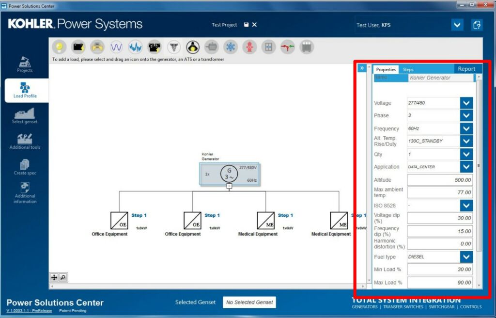
The Properties tab shown on the Load Profile page allows you to update/edit specific components of your power system. Each of the fields shown in the Properties tab, although not all are required, need to have a value in place.
You can define the following variables for your power system: Voltage, Phase, Frequency, Alt. Temp. Raise/Duty, Qty (Number of generators used/needed in system), Application, Altitude, Max ambient temp, ISO 8528 (The design and performance criteria arising out of the combination of an Internal Combustion engine and an Alternating Current generator when operating as a unit, shown in G1, G2 and G3 levels), Voltage dip (%), Frequency dip (%), Harmonic distortion (%), Fuel type, Min Load (%), Max Load (%), Seismic (Need to comply with seismic building requirement codes?), UL 2200 (Generator assemblies rated 600 volts or less that are intended for installation and use in ordinary locations, in accordance with the National Electrical Code NFPA 70 and o CSA (Need to comply with the Canadian Standards Association?).
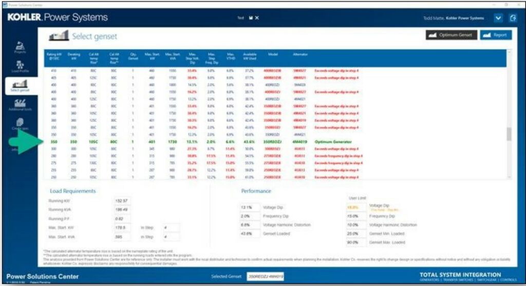
After you have fully customized each component in your power system, click on the Select Genset tab to view each of the compatible generators with your project specific needs. The program will also highlight which of the possible configurations is optimal for your project (see the image below, where the recommendation is highlighted with the green arrow).
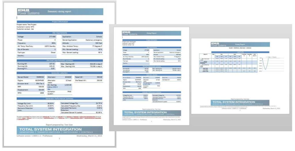
Then you will be able to create a summary, detailed, or single line diagram report, of the selected generator.
Kohler Power Solution Center supplemental tools.
With the Genset tab selected, additional parameters can be set to establish the environment the system will be deployed into, and allow you to configure the exhaust system, input fuel pipe sizing calculations for gas systems, and also select the optimum room size for proper and safe operation. In this section you will have access to the following tools:
- Generator Sound Level Calculator: Select the genset model then enter the distance to calculate the sound level based upon the type of enclosure that will be used. Note that calculations are based upon a 180-degree field, travelling in a straight line unimpeded and undeflected. Consider the site location.
- Exhaust System Piping Calculator: Use the dropdown box to change the default genset model. Exhaust values will change accordingly. User inputs allow you to change silencer type, pipe length, and the quantity of bends.
- Pipe Sizing Calculator for Gas Systems: Use the dropdown box to change the default genset model, inlet fuel pressure, and gas type. User Inputs allow you to change pipe length, quantity of bends, tees, unions, and valves.
- Genset Room Size Calculator: Use the dropdown box to change the default genset model. Room dimension values will change accordingly.
Important note: The analysis provided from Kohler Power Solution Center are for reference only. The installer must work with the Brags & Hayes Generators Customer Service team and technician to confirm the requirements when planning the installation.
We will be here to help you!


