In the world of power generation, where reliability is paramount, the role of cables in ensuring seamless energy flow cannot be overstated.
When it comes to install a power generator to its load, determining the perfect cable number is a matter of technical precision and engineering expertise.
This article delves into the intricate world of selecting the optimal cable number for install a power generator, shedding light on the underlying principles and factors that come into play.
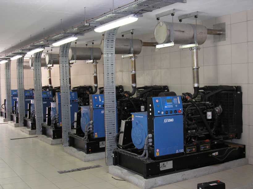
The optimal cable number to install a power generator depends on the generator’s amperage rating, which is determined by the amount of electricity it produces. The power cord you use should match the most powerful outlet on your generator. For instance, if your generator has a 50-amp outlet, you’ll need a 50-amp power cord. If it has a 20-amp outlet, you’ll need a 20-amp cord. Choosing the wrong cord can result in wasted power or damage to your generator and appliance.
The voltage and frequency of the generator are not directly related to the optimal cable number.
However, it’s important to select the right generator cord shape. The plugs and connectors are purposely designed in different shapes to help prevent an electrical overload. For example, 30-amp plugs come in two varieties: 3-prong and 4-prong. The 3-prong plugs carry 120 volts only, while the 4-prong plugs carry 120/240 volts. The 4-prong varieties are becoming more popular because homes are increasingly starting to carry 240-volt outlets or appliances.
For a proper installation, there must be a compatibility between the load, the specifications of the ATS (Automatic Transfer Switch) used in the installation, and the specifications of the generator. Additionally, these characteristics must be in line with the type of cable chosen for the installation.
Cable Sizing Basics
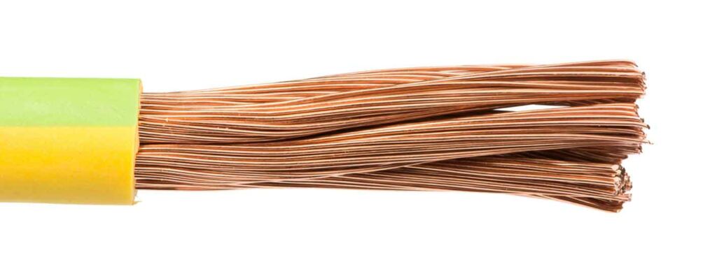
Current-Carrying Capacity
To calculate the current-carrying capacity of a cable (The ampacity of a cable is the maximum amount of current that it can safely carry without overheating), you need to consider several factors, including the cable’s cross-sectional area, the type of insulation, and the ambient temperature. The current-carrying capacity of a cable is determined by its ability to dissipate heat generated by the current flowing through it. The heat dissipation is affected by the cable’s cross-sectional area, which determines the amount of surface area available for heat dissipation.
The current-carrying capacity of a cable can be calculated using the following formula:
I = K x A x (Tc – Ta)^(3/2)
- I is the maximum current-carrying capacity of the cable in amperes.
- K is a constant that depends on the type of insulation used in the cable.
- A is the cross-sectional area of the cable in square millimeters.
- Tc is the maximum allowable conductor temperature in degrees Celsius.
- Ta is the ambient temperature in degrees Celsius.
The constant K can be found in tables provided by cable manufacturers or regulatory bodies. These tables typically provide values for different types of insulation and ambient temperatures.
For example, here a calculation of the maximum current carrying capacity according to VDE 0298-4:2023-06:
- Cable type: CC 500
- Conductor article: L0200-0315
- Temperature range: up to +70°C
- Rated voltage: Uo/U: 300/500V
- Construction: 3 G 1,5 mm²
- Application: For this installation cable the current carrying capacity is required at +50°C ambient temperature, two loaded cores and laying with three other cables on one floor.
The four cables have the same dimension and touch each other.
Tables of VDE 0298-4 to be observed: Table 10, 11, 17 and 22.
Current carrying capacity with two wires 1.5mm² loaded at the same time at up to +30°C according to table 10 and 11/5: 18A
Factor for deviating ambient temperature +50°C according to table 17: 0.71 (18 A x 0.71 ≈ 12.8A)
Factor for laying four of these lines on the floor with contact: 0.75 (12.78A x 0.75 ≈ 9.6A).
The current load for the described line should not exceed a value of 9.5A.
Voltage Drop Considerations
When selecting the correct cable number to install a power generator, it’s important to consider voltage drop. Voltage drop is the reduction in voltage that occurs when electricity flows through a cable. The amount of voltage drop depends on the length of the cable, the amount of current flowing through it, and the cable’s resistance. If the voltage drop is too high, it can cause damage to your generator and appliances.
To calculate voltage drop, you can use the following formula:
Vd = (2 x L x I x R) / 1000
Where:
- Vd is the voltage drop in volts.
- L is the length of the cable in feet.
- I is the current flowing through the cable in amperes.
- R is the resistance of the cable in ohms per 1000 feet.
The National Electrical Code (NEC) recommends that voltage drop should not exceed 5% for branch circuits and 3% for feeders. To ensure that your generator operates efficiently and safely, you should choose a cable size that keeps voltage drop within these limits.
When installing high-quality products with the assistance of professional services and engineering expertise, the user manual provides installation specifications that consider all these factors. It presents a standard installation plan that defines the distances and types of cables to be used. We strongly advise following this standard installation whenever possible. If meeting these distances is not feasible, it becomes necessary to rely on specialized engineers who can calculate the variables and determine the appropriate cable for your specific installation.
The Cable Number Dilemma
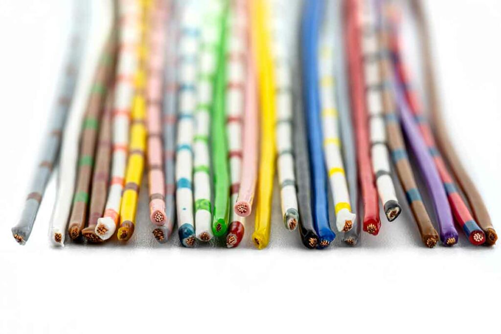
Overloading Risks
Undersizing the cable in a power generator installation can lead overloading.
Overloading a cable in a power generator installation can lead to several risks, including:
Fire hazard: Overloading a cable can cause it to overheat and potentially ignite nearby flammable materials.
Electrical hazards: Overloading a cable can cause the circuit breaker to trip or the fuse to blow, which can lead to electrocution hazards.
Equipment damage: Overloading a cable can damage your generator and appliances.
Oversizing Cables
Oversizing a cable in a power generator installation can lead to several risks, including:
Higher cost: Oversizing the cable can result in higher material and installation costs.
Difficulty terminating: Larger cables can be more difficult to terminate, which can lead to poor connections and increased resistance.
Increased weight: Larger cables are heavier and bulkier, which can make them more difficult to handle and install.
Reduced flexibility: Larger cables are less flexible, which can make them more difficult to route and install.
In addition, oversizing the cable can also lead to reduced efficiency and increased voltage drop. The amount of voltage drop depends on the length of the cable, the amount of current flowing through it, and the cable’s resistance. If the voltage drop is too high, it can cause damage to your generator and appliances.
To avoid the risks of undersizing or oversizing cable in your installation, it’s important to choose the right cable size that matches the most powerful outlet on your generator and ensures that voltage drop is within acceptable limits. The National Electrical Code (NEC) recommends that voltage drop should not exceed 5% for branch circuits and 3% for feeders. You should also ensure that the cable is properly grounded and that the grounding connections are tight. Always check with your manufacturer’s data before detailed engineering.
Technical Guidelines
NEC Guidelines
The National Electrical Code (NEC) provides guidelines for the installation of power generators. Article 445 of the NEC contains the electrical installation and other requirements for generators. These rules include such things as where generators can be installed, nameplate markings, conductor ampacity, and disconnect requirements. Here are some of the key guidelines:
Location: Generators should be installed in a location that is accessible for maintenance and repair, but also protected from weather and flooding.
Nameplate markings: The generator should have a nameplate that provides information such as the manufacturer’s name, model number, serial number, and rated output.
Conductor ampacity: The ampacity of the conductors used to connect the generator to the load should be based on the generator’s output and the length of the conductors.
Disconnect requirements: A disconnecting means should be provided to isolate the generator from all sources of supply.
It’s important to note that these are just some of the guidelines provided by the NEC. Always check with your manufacturer’s data before detailed engineering.
IEC Standards
The International Electrotechnical Commission (IEC) publishes international standards, technical guides, and reports that are the basis or a reference of utmost importance for any national and European standardization activity. The IEC has issued a range of standards that set out the performance, manufacture, and design of AC generators. These standards cover topics such as the rating and performance of generators, the design and construction of generator sets, and the installation and maintenance of generators.
Here are some examples of IEC standards related to power generator installations:
IEC 60034-1: This standard specifies the requirements for rotating electrical machines, including generators.
IEC 60947-6: This standard provides guidance on the design and testing of low-voltage switchgear and control gear for use with generators.
Please note that this is not an exhaustive list of IEC standards related to power generator installations. Always check with your manufacturer’s data before detailed engineering.
Local Codes
Before installing a power generator, it is essential to have knowledge of the local codes and regulations as they can impact the type, size, location, and wiring of the generator. Each region and country may have different safety, noise, emissions, and grid connection requirements.
For instance, California (USA) has specific criteria and procedures for licensing new emergency and temporary power generators. In certain countries in Latin America, the electricity sector is governed by regulatory agencies. It is crucial to adhere to the local codes and regulations to prevent fines, penalties, or legal complications.
The Importance of Redundancy
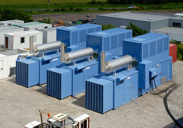
The importance of wiring redundancy for installing a power generator depends on the level of reliability and availability required for the power system.
Wiring redundancy means having more than one path for the electrical current to flow between the power source and the load, so that if one path fails, another one can take over. This can prevent power outages, equipment damage, and safety hazards caused by faults or failures in the wiring system.
Some cases where wiring redundancy is important for installing a power generator are:
Critical facilities that need uninterrupted power supply, such as hospitals, data centers, military bases, airports, etc. These facilities may use parallel redundancy, which means having two or more generators that can operate simultaneously or independently to provide power to the load. They may also use tie breakers and segmented bus to connect different power sources and loads, and to isolate parts of the system for maintenance and repair.
Power plants that use synchronous generators to produce electricity. These generators need to be protected from faults and disturbances that can affect their stability and operation. A redundant design of relay protection system can reduce the probability of inappropriate operation of relay protection schemes.
Power distribution systems that need to maintain power quality and reliability for customers. These systems may use parallel redundancy to increase the capacity and efficiency of the system, as well as to provide backup power in case of a utility outage.
Choosing the Right Cable Type
As mentioned earlier in this article, the selection of the suitable cable gauge or thickness is crucial when wiring your power generator. However, another significant consideration is the choice of cable type.
The selection of the appropriate cable type for wiring the power generator to the ATS and load is influenced by various factors including voltage, current, temperature, environment, and installation method of the system. Below are some technical guidelines to assist in decision making:
1. Copper vs. Aluminum: The materials commonly used for power cables are copper and aluminum. Copper possesses superior conductivity, durability, and reliability compared to aluminum. However, it is also more expensive and heavier. Aluminum, on the other hand, has lower conductivity but is cost-effective and lightweight. Special terminations and larger cross-sectional areas are necessary for aluminum cables to prevent corrosion and overheating. Choosing between copper and aluminum depends on the system’s cost, performance, and weight requirements.
2. Armored Cables: Armored cables are power cables that incorporate a metal sheath or armor around the conductors. This metal sheath provides mechanical protection and grounding. Armored cables are suitable for environments with potential physical damage, moisture, fire, or rodent exposure. They can be installed in various settings such as direct burial, underground ducts, cable trays, or open air. However, armor cables tend to be more expensive and heavier than non-armored options, and their installation may require specialized tools and fittings.
3. Flexible vs. Rigid Cables: Flexible cables have multiple strands of conductors, allowing them to bend and twist easily. They are ideal for applications that require frequent movements, vibrations, or tight bends, such as in generator sets, motors, or appliances. In contrast, rigid cables have solid or few strands of conductors that are stiff and difficult to bend. Rigid cables are suitable for applications that require withstanding high mechanical stress, like overhead lines, underground systems, or fixed installations. Flexible cables are typically more expensive and exhibit higher resistance compared to rigid cables, but they offer easier installation and handling.
To determine the appropriate cable type for your power generator installation, consult the manufacturer’s specifications, local codes and regulations, as well as professional electricians. Additionally, consider environmental conditions, safety factors, and maintenance requirements specific to your system.
Cable Insulation and Protection
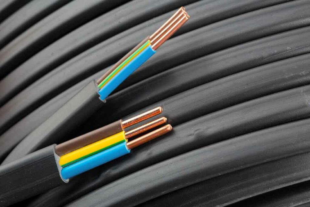
Choosing the right cable insulation and protection for wiring the power generator to the ATS and load depends on several factors, such as the voltage, current, temperature, environment, and installation method of the system. Cable insulation and protection are important to prevent electrical hazards, such as short circuits, shocks, fires, and arc flashes.
Some of the cable insulation and protection types that you may consider are:
UV Protection: UV protection is a coating or layer that protects the cable from ultraviolet (UV) radiation, which can degrade the cable insulation and cause cracking, brittleness, and loss of mechanical strength. UV protection is especially important for outdoor or exposed installations, where the cable is subject to direct sunlight or artificial UV sources. Some of the materials that provide UV protection are polyethylene (PE), cross-linked polyethylene (XLPE), ethylene propylene rubber (EPR), and polyvinyl chloride (PVC).
Chemical Resistance: Chemical resistance is the ability of the cable to resist corrosion, deterioration, or damage caused by exposure to chemicals, such as acids, alkalis, oils, solvents, or gases. Chemical resistance is important for installations where the cable is in contact with or near corrosive substances, such as in industrial plants, refineries, mines, or sewage systems. Some of the materials that provide chemical resistance are fluorinated ethylene propylene (FEP), polytetrafluoroethylene (PTFE), ethylene tetrafluoroethylene (ETFE), and chlorinated polyethylene (CPE).
To choose the right cable insulation and protection for your power generator installation, you should consult the manufacturer’s specifications, local codes and regulations, and professional electricians. You should also consider the environmental conditions, safety factors, and maintenance requirements of your system.
You can also refer to following references:
IEEE Guide for the Design and Installation of Cable Systems in Substations: This guide covers the design, installation, and protection of wire and cable systems in substations, with the objective of minimizing cable failures and their consequences.
11 kV cable insulation rating – Electric power & transmission & distribution – Eng-Tips: This forum thread discusses the cable insulation rating for 11 kV systems with different grounding methods.
Electrical Design Handbook – ITER: This handbook provides guidelines and recommendations for the electrical design of ITER systems.
Proper Cable Termination
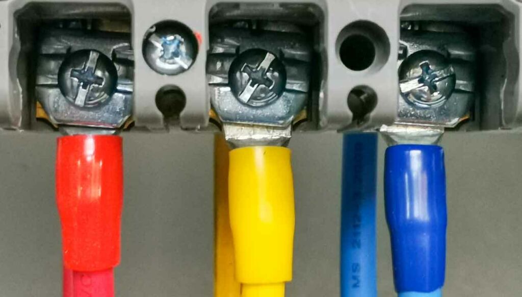
Choosing the right proper cable termination for wiring the power generator depends on several factors, such as the cable type, size, material, voltage, current, environment, and installation method of the system.
Cable termination is the process of connecting the cable to a device or another cable, using suitable connectors, lugs, and accessories. Cable termination is important to ensure a reliable and safe electrical connection, as well as to protect the cable from environmental factors, such as moisture, dust, heat, or corrosion.
Some of the aspects that you may consider for choosing the right proper cable termination are:
Cable Lugs: Cable lugs are metal fittings that are crimped or soldered to the end of the cable conductor to provide a secure and durable connection to a terminal or a connector. Cable lugs are available in different shapes, sizes, and materials, depending on the cable type and application. Some of the common types of cable lugs are ring, fork, pin, spade, and butt lugs1. Some of the factors that affect the selection of cable lugs are:
Cable type and size: The cable lug should match the cable type (copper or aluminum), size (cross-sectional area), and configuration (single or multi-stranded). The cable lug should also have enough length and diameter to accommodate the conductor without leaving any gaps or excess material.
Crimping tool and die: The cable lug should be compatible with the crimping tool and die that are used to attach it to the cable. The crimping tool and die should be selected according to the manufacturer’s specifications and instructions. The crimping tool should apply enough force and pressure to create a strong and uniform crimp without damaging the cable lug or conductor.
Terminal or connector type: The cable lug should fit snugly into the terminal or connector that it is connected to. The cable lug should also have the appropriate shape and size to match the terminal or connector design. For example, ring lugs are suitable for bolted connections, while pin lugs are suitable for plug-in connections.
Connectors: Connectors are devices that join two or more cables or wires together, using mechanical or electrical means. Connectors are available in different types, such as splices, couplers, adapters, plugs, sockets, etc. Some of the factors that affect the selection of connectors are:
Cable type and size: The connector should match the cable type (copper or aluminum), size (cross-sectional area), and configuration (single or multi-conductor). The connector should also have enough capacity and rating to handle the voltage and current of the system.
Insulation and protection: The connector should have adequate insulation and protection to prevent electrical hazards, such as short circuits, shocks, fires, and arc flashes. The insulation and protection should also be suitable for the environment where the connector is installed, such as indoor or outdoor, wet or dry, hot or cold, etc. Some of the common types of insulation and protection are tape, heat shrink tubing, resin, armor, etc.
Installation method: The connector should be easy to install and maintain, using proper tools and techniques. The installation method should also comply with the local codes and regulations for safety and quality standards. Some of the common installation methods are crimping, soldering, twisting, clamping, etc.
Torque Specifications: Torque specifications are the recommended values of force and angle that are applied to tighten a bolted connection between a cable lug and a terminal or a connector. Torque specifications are important to ensure a secure and reliable electrical connection, as well as to prevent damage to the cable lug or terminal or connector. Torque specifications vary depending on the type and size of the cable lug and terminal or connector. Torque specifications should be followed according to the manufacturer’s instructions and guidelines.
To choose the right proper cable termination for your power generator installation, you should consult the manufacturer’s specifications, local codes and regulations, and professional electricians. You should also consider the environmental conditions, safety factors, and maintenance requirements of your system.
You can also refer to some of the web search results that I found for you:
POWER CABLE INSTALLATION GUIDE: This guide provides installation information for extruded dielectric power cable systems.
Power Cable Splicing and Terminating Guide: This guide provides splicing and terminating techniques for power cables using 3M products.
Method Statement Title: Installation of Generator and ATS: This document provides a method statement for installing a generator and an ATS.
Practical HV Cable Jointing and Terminations for Engineers and Technicians: This book provides practical guidance on high voltage cable jointing and terminating.
Safety Measures

Safety measures are essential for wiring the power generator, as they can prevent fire hazards and protect personal safety, as well as ensure the proper functioning and performance of the system. Some of the safety measures that you should take into account are:
Fire hazards
Fire hazards can occur due to overheating, short circuits, sparks, or fuel leaks in the generator or the wiring system.
To prevent fire hazards, you should:
- Keep fuel away from the generator, while the generator is running. Avoid refueling while the generator is in operation and keep a fire extinguisher easily accessible.
- Use the standard lock out technique as recommended by the manufacturer when working on the generator so it won’t accidentally turn on.
- Use proper cable insulation and protection to prevent electrical hazards, such as tape, heat shrink tubing, resin, armor, etc.
- Use suitable connectors, lugs, and accessories that match the cable type, size, material, voltage, and current of the system.
- Follow the torque specifications for tightening the bolted connections between the cable lugs and the terminals or connectors.
- Install the generator outdoors only, in a well-ventilated area at least 20 feet (7 metres) from all doors, windows, and vent openings.
Personal safety
Personal safety can be compromised due to electric shocks, burns, injuries, or carbon monoxide (CO) poisoning in the generator or the wiring system. To protect personal safety, you should:
- Wear appropriate protective equipment, such as gloves, goggles, boots, etc., when working on the generator or the wiring system.
- Turn off the main power supply and disconnect all loads before installing or servicing the generator or the wiring system.
- Never attach your generator system directly to your electrical mains connection. Always use a transfer switch in between. Seek the help of a qualified electrician for installing your generator.
- Inspect the electrical cords for damages, cuts and abrasions. Make sure they are plugged directly into the generator or a heavy duty outdoor-rated extension cord. The cords should be checked for cuts, tears and that the plug has all three prongs, especially a grounding pin.
- Make sure to install carbon monoxide (CO) alarms. Follow manufacturer’s instructions for correct placement and mounting height. Do not stand or sit downwind of generator exhaust. If you can smell exhaust, you are inhaling it.
Grounding and bonding
Grounding and bonding are important to provide a low-resistance path for fault currents to flow to earth and to maintain a common reference potential for different parts of the system. To ensure proper grounding and bonding, you should:
- Connect a grounding electrode conductor from the frame of the generator to a grounding electrode that is located as close as possible to where it is driven into earth.
- Use copper conductors that are properly sized and insulated for grounding purposes.
- Use suitable grounding clamps or connectors that are compatible with the grounding electrode conductor and the grounding electrode.
- Bond all metal parts of the generator enclosure and all non-current carrying metal parts of equipment supplied by the generator together using an equipment grounding conductor that is properly sized and insulated.
- Use suitable equipment grounding clamps or connectors that are compatible with the equipment grounding conductor and the metal parts.
These are some of the general safety measures that you should consider for wiring the power generator to the ATS and load. However, you should always consult the manufacturer’s specifications, local codes and regulations, and professional electricians for specific guidance and recommendations.
Finding the ideal cable number for a power generator installation is a delicate equilibrium of both science and safety. Cable number, which pertains to the size or cross-sectional area of the cable conductor, influences important aspects like the cable’s capacity to carry current, voltage drop, and resistance. Opting for a cable number that is too small poses risks such as overheating, fire hazards, and lackluster system performance. Conversely, selecting a cable number that is too large results in wasteful use of materials, increased costs, and challenges during installation and termination.
Therefore, when determining the ideal cable number for a power generator installation, one must carefully consider numerous factors covered in this article. These factors include the generator’s power rating, cable length and type, ambient temperature and environment, installation method and configuration, as well as adherence to local codes and regulations. Furthermore, if your installation deviates from standard practices or lacks documentation in the generator user manual, it becomes imperative to utilize appropriate formulas and tables for calculating the cable number, taking these factors into account.
Don’t hesitate to reach out for any further information or assistance regarding to professional generator installation. Contact us at the phone number +1.954.657.7777, or write to us at info@bnhgenerators.com, and we will gladly help you.


