Modern electrical generating systems are seldom used as standalone units. More often than not, they need to interface with peripheral devices, other generating systems, building-management systems, or remote monitors. Consequently, various technologies have been developed to facilitate communication between these systems and other equipment. For engineers tasked with specifying, installing, or maintaining these systems, it is imperative to understand these communication technologies to meet operational and building requirements effectively.
- What existing systems need to communicate with the electrical generating system?
- What data or status indications are required from the electrical generating system?
- What specific information is needed? Where does this data need to be sent?
- What is the distance between the electrical generating system and the end device?
- What is the communication hardware and protocol employed by the building-management system devices (or other systems) that will connect to the electrical generating system?
- What hardware and protocol should be specified to operate with the existing systems?
This post provides insights into digital communication systems used in electrical generating systems and emphasizes why answering these questions is critical. With this knowledge, stakeholders can develop comprehensive, well-thought-out specifications for the electrical generating system, avoiding pitfalls during installation and use.
Components of a Communication System in Electrical Generating Systems.
A communication system within an electrical generating system consists of two fundamental components: hardware and protocol. Think of hardware as the tangible devices, while protocol functions as the software that facilitates data flow between hardware components.
In a human model, the hardware represents people, and the protocol is the language used for communication. See Figure 1 for a visual representation. In human communication, language differences can present challenges, similar to the challenges faced by communication networks due to variations in protocols. Additionally, factors like speed can impact efficacy—if someone speaks too quickly or too slowly, comprehension can be difficult. In a similar way, communication networks may experience issues like interrupted conversations or discussions that veer off-topic. Furthermore, if there is a substantial distance between the entities, additional hardware becomes necessary, akin to using a telephone for long-distance communication.
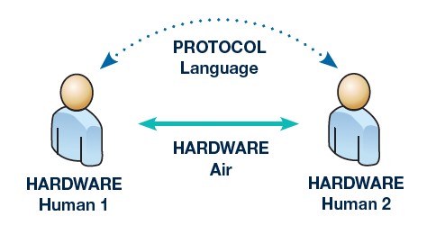
Communication between electronic devices parallels human communication, complete with complexities and issues.
In electronic communication systems, the hardware comprises digital circuitry that meets precise timing and power standards established by international committees. Due to this standardization, hardware components are relatively straightforward. A common example of communication hardware is a USB cable and connectors used between a PC and a printer. The protocol, or language, used by electronic devices to communicate over hardware can vary widely. Multiple protocols may communicate through a single type of hardware, and some protocols are defined as industry standards while others are proprietary. Standard protocols, like those used with USB memory sticks, allow interoperability across different systems. Conversely, proprietary protocols are restricted, allowing communication only within systems designed by the same developer. For instance, in-vehicle communication systems for mechanics’ diagnostic computers use proprietary protocols unique to each auto manufacturer.
When preparing an electrical generation system specification, it is essential to gather communication hardware and protocol information for every device or system that needs to interface with the new system. This data collection ensures proper system functionality and identifies any necessary adapters to convert between different types of hardware and protocols.
Common Communication Hardware/Networks and Protocols in Electrical Generation Systems
RS-485 Serial Networks (Hardware)
The RS-485 standard defines the physical connection for serial networks and should not be confused with the now less common RS-232 standard, which was used primarily in computers. Developed in the early 1970s, RS-485 remains widely used in industrial communication products. RS-485 specifies a physical twisted-pair connection with specific configurations for data transmission on each connection point. Kohler Power Systems recommends Belden cables for RS-485 connections. However, RS-485 does not specify the physical characteristics of connection points, often utilizing Euroblock connectors in Kohler systems. These connectors, which employ screw terminals, offer a convenient method for connecting and disconnecting devices.
A crucial aspect of RS-485 is the necessity for a terminating resistor to prevent message interference, ensuring data integrity by ensuring that communicated messages stop at the last device instead of reflecting back, potentially interfering with subsequent messages. Specifications for the generation system must include details on ensuring proper operation when using an RS-485 serial network.
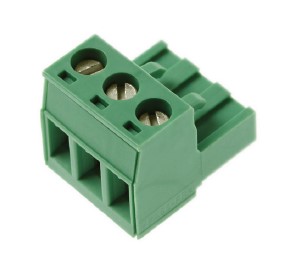
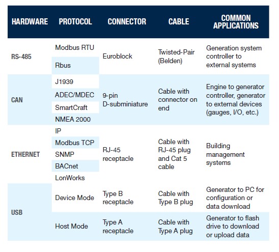
HARDWARE, PROTOCOL, CONNECTOR, AND CABLE EXAMPLES, RS-485:
Protocol: Modbus RTU, Rbus, J1939
Connector: Euroblock
Cable: Twisted-Pair (Belden)
Applications: Generation system controller to external systems
CAN
Protocol: ADEC/MDEC, SmartCraft, NMEA 2000, IP
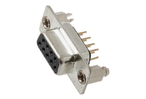
Connector: 9-pin D-subminiature
Cable: Cable with connector on the end
Applications: Engine to generator controller, generator to external devices (gauges, I/O, etc.)
Ethernet
Protocol: Modbus TCP, SNMP, BACnet, LonWorks
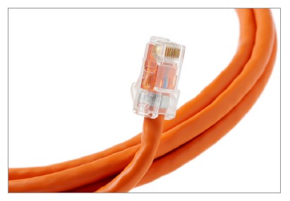
Connector: RJ-45 receptacle
Cable: Cable with RJ-45 plug and Cat 5 cable
Applications: Building management systems
USB
Protocol: Device Mode, Host Mode
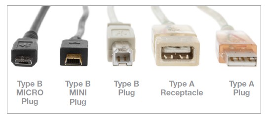
Connector: Type B receptacle (Device Mode), Type A receptacle (Host Mode)
Cable: Cable with Type B plug (Device Mode), Cable with Type A plug (Host Mode)
Applications: Generator to PC for configuration or data download (Device Mode), Generator to flash drive for data transfer (Host Mode)
RS-485 Considerations
RS-485 can be a cost-effective choice for short distances, although twisted-pair cables may become costly over longer distances, especially if encased in conduit.
RS-485 can operate over distances up to 1200 meters (4000 feet).
RS-485 performs well in electrically noisy environments.
RS-485 offers relatively lower communication speeds, which may be noticeable if large amounts of data are being transferred, although this is often not an issue.
Modbus RTU (Protocol)
Modbus RTU is a serial communication protocol developed in the late 1970s, prominently used over the RS-485 hardware layer. It is commonly implemented in building-management systems like SCADA and other systems that support the protocol. Modbus RTU requires a primary (master) device to initiate communication, while secondary (slave) devices respond to these communications.
Rbus (Protocol)
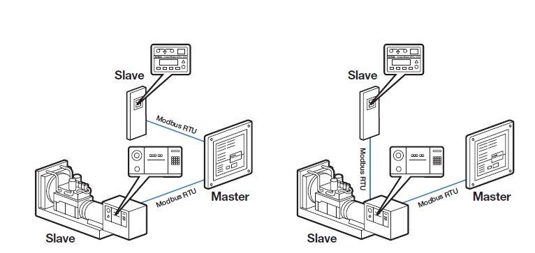
Rbus is a proprietary Kohler protocol designed mainly for residential and light commercial products. It communicates over the RS-485 hardware layer and integrates multiple Kohler devices such as generators, transfer switches, programmable interface modules, and load control modules. Being proprietary, it does not communicate with non-Kohler systems.
CAN Networks (Hardware)
CAN, short for Controller Area Network, originated in the automotive industry and has been adopted in power generation through its use in engines. It defines the physical connection characteristics like voltage, current, and number of connectors but does not specify the mechanical features of connection points. Commonly used connectors include 9-pin D-subminiature connectors, though RJ45 connectors may also be employed in Kohler implementations. CAN, like RS-485, requires a terminating resistor to ensure that messages don’t reflect and interfere with subsequent communications. CAN networks in generating systems are often used to communicate with the engine, remote I/O boards, and external gauges. Kohler typically uses separate CAN networks for the ECM and other communications to reduce network “chatter.”
CAN Considerations
- CAN is a cost-effective hardware choice due to its common components and short cable distances.
- CAN operates effectively over shorter distances (up to 40 meters/120 feet).
- CAN provides excellent immunity to electrically noisy environments.
- CAN features a multinode architecture, allowing devices to communicate without a single point of failure and offers good communication speeds.
Ethernet Networks (Hardware)
Ethernet, familiar to many as a means for Internet access, is also employed for communication in generating systems. It can be wired, using an RJ-45 connector at the end of a Cat 5 cable, or wireless via Wi-Fi. Ethernet networks require each device to have a unique MAC address, creating security concerns that necessitate additional measures such as firewalls. Ethernet is highly scalable, supporting extensive networks and long distances, and integrates well with existing IT infrastructure. Protocols such as IP, Modbus TCP, SNMP, BACnet, and LonWorks commonly operate over Ethernet networks.
Ethernet Considerations
- Ethernet can be more costly due to the additional equipment needed, like routers.
- Involvement of IT experts is often necessary to configure devices.
- Ethernet supports large networks and long distances.
- It integrates seamlessly with networking infrastructure, providing excellent scalability.
- Ethernet features high communication speeds and resilience against single points of failure.
Internet Protocol (Protocol)
The most common Ethernet protocol is the Internet Protocol (IP), assigning each device an IP address. Unlike MAC addresses, which are fixed, IP addresses can change depending on the network segment. Devices can have either static IP addresses or dynamic IP addresses assigned via DHCP. Specifying whether IP addresses will be static or dynamic is important for system stability, as changing IP addresses can disrupt communication with remote monitoring systems.
Modbus TCP (Protocol)
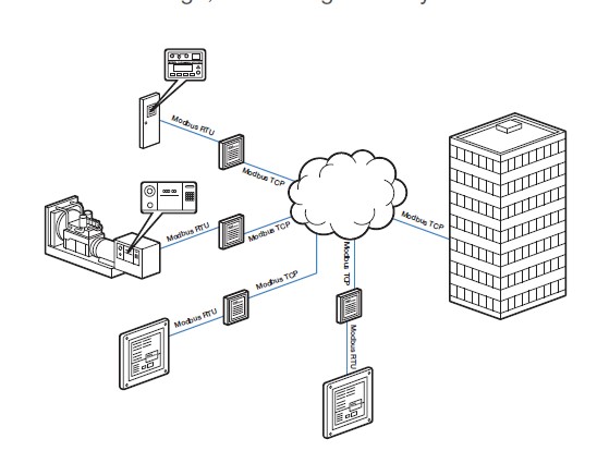
Modbus TCP enables Ethernet-based Modbus communication, often using Modbus-to-Ethernet converters to extend network distances and facilitate multiple master devices communicating with secondary devices.
SNMP (Protocol)
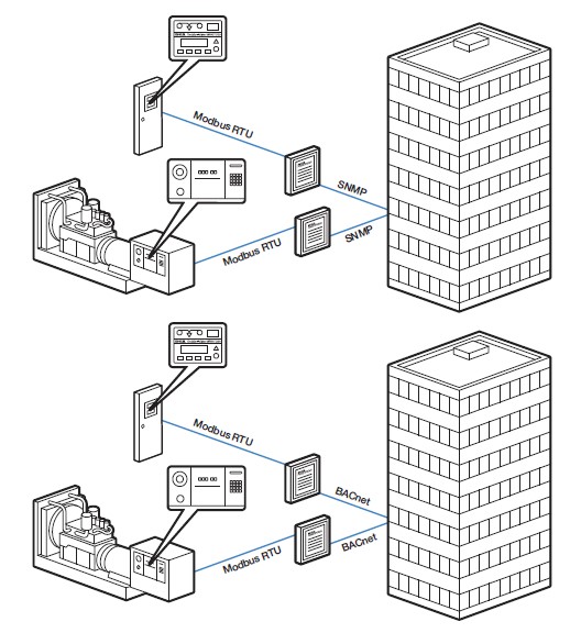
SNMP (Simple Network Management Protocol) is an Ethernet protocol used by building-management systems to monitor device messages. In generating systems, SNMP monitors for events like generator faults and sends these events to management systems for alert generation.
BACnet (Protocol)
BACnet (Building Automation and Control Networks) is a protocol commonly used by building-management systems to monitor device messages. It shares similarities with SNMP, in that it supports multiple hardware layers, including Ethernet.
LonWorks (Protocol)
LonWorks (Local Operation Network) is another building-management protocol, designed specifically for control applications. Although less common than BACnet, it is emerging as a viable option for building automation.
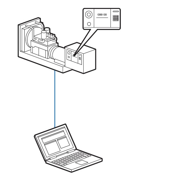
USB has become commonplace in personal computers and is now used in electrical generating systems for computer access and data transfer. It supports two modes of communication: device mode for interfacing with PCs and host mode for data transfer via flash drives.
USB Communication (Hardware)
USB Considerations
USB is widely used and offers very fast communication speeds.
It operates over shorter distances and supports communication between only two devices at a time.
In USB device mode, generator controllers communicate with PCs using software like KOHLER® SiteTech, which requires a Type B connector. This setup is available to Kohler-certified technicians for configuration and data download.
In USB host mode, generator controllers can be reprogrammed or data-logged using a flash drive, requiring a Type A connector. This mode is also used in various Kohler generator controllers.
The variety of hardware and protocols available for generator and building systems necessitates careful preparation and collaboration among all stakeholders. Engineers specifying electrical generation systems should involve key stakeholders to identify existing devices and systems needing communication with the new system. Using this document as a guide, stakeholders can catalog current systems’ hardware and protocol, determine communication needs, and map device locations. Comprehensive planning and answering key questions about hardware and protocols will lead to well-designed generator system solutions, resulting in better functionality and satisfied customers.
Consulting with Brags & hayes Generators Support team can further ensure that your electrical generating system specification and purchase meet all required functionalities.


